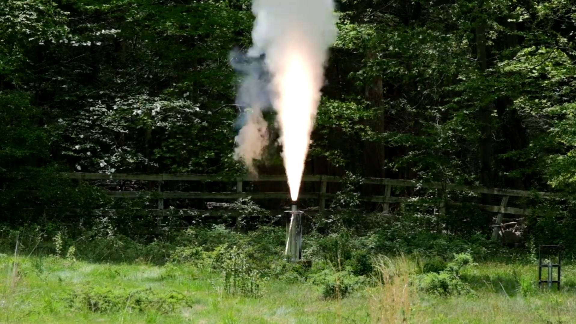
Reliant Robin: ABLATE-N3200
The Reliant Robin N3200 was the initial testbed for a fundamentally new method for building rocket motors. By replacing typical convolute-wound paper phenolic insulators with a cast rubbery insulator, higher performance and repeatability can be attained. With new building techniques comes new challenges, and this motor set out to discover these unknowns and improve upon them.
Three primary goals were set for this project:
Successfully cast a rubbery insulator layer along the inner circumference of the motor casing.
Formulate the rubbery layer so it can resist erosion from high temperature, high pressure gases in the motor casing.
Verify the design integrity of a new forward finocyl grain geometry.
The overall motor design is shown below in the CAD cross section below:
Overview
This page will discuss the motor architecture and design philosophy, as well as document the manufacturing process and report lessons learned.
Spin Casting
To cast the aforementioned rubbery insulator layer, a machine known as a “spin caster” was first designed and constructed. The intent of this machine is straightforward: to spin the rocket motor casing at high speeds for an extended period of time. Shown below is a CAD mockup of the spin caster machine:
Complete spin caster assembly.
The motor casing rests on a series of ball bearings and is constrained vertically with an additional ball bearing. A 3D-printed sprocket is affixed to the motor casing which is coupled to another sprocket on an electric motor with a timing belt. To ensure the motor casing is constrained laterally, a grounded ball bearing is located at either end of the motor casing. To learn more about the spin caster, visit this page.
The insulator layer is HTPB-based, which is the same polymer system used in propellant. This ensures a high quality chemical bond forms between the cast propellant and insulator layer. To mitigate insulator erosion and to augment insulative properties, silica, carbon black, and Kevlar fibers are added to the insulator. The insulator begins its life as a liquid, which is then spun at high speeds (~300 rpm) for up to 12 hours. The centripetal force leads to a coating of even thickness throughout the length of the casing. Although some oxy-acetylene torch testing had been run on the insulator, its performance in motor conditions was unknown so it was made to be excessively thick to guarantee its success. The picture below shows the finished insulator layer:
Cast insulator layer of uniform thickness.
Aft Inhibitor Casting
After the insulator was cast, another inert rubbery component needed to be manufactured: the aft inhibitor. Similar in composition to the insulator, this layer serves two purposes. First, it prevents the aft face of the propellant from burning. Second, it acts as the seal between the propellant and the nozzle. If gas permeates this joint, it will create a direct path to the casing wall, resulting in a quick and abrupt thermal failure. This was cast using a positive mold, which was then removed once the component finished curing. A photo of this complete part is shown below:
Cast aft inhibitor.
Grain Geometry & Propellant Casting
The propellant grain geometry was designed with two factors in mind: first, it needed to minimize mass flux of combustion gas exposed to the insulator. The more gas exposed to the insulator, especially at higher velocities, the higher the erosion rate of the insulator. Second, it needed to provide a neutral burning profile. For future motors which will be used in flight configurations, a neutral or even regressive burn profile is desired to minimize aerodynamic loading on the flight vehicle.
To satisfy both these requirements, a forward finocyl was used. With a forward finocyl, none of the insulator mass flux problems will be realized and all of the neutral burning characteristics will be retained. Due to physical limitations, however, this meant that the mandrel needed to be composed of two pieces. The cylindrical and tapered aft sections would be removed from one side of the motor, and the finocyl would be removed from the other. The cast propellant is shown below:
Cast Reliant Robin propellant.
Testing and Results
With all polymeric components cast, it was time to button up the motor and prepare it for test firing. Each closure was retained with 16x 0.25” high strength steel dowel pins. Temperature indicating stickers were placed at potential hot spots that the motor may produce. After firing, the motor was sectioned in half to analyze the insulator condition. These photos and the thrust curve are shown below:
Delivered thrust/pressure trace.
Aft end cross section.
Forward and aft end cross sections.
Aft end close up.
The thrust curve ended up as an overall regressive burn with a large pressure spike seen at the beginning of the burn. The regressive burn was caused by the erosive phenolic nozzle used. In future motors, a non-erosive nozzle material will be used to keep the thrust trace predictable. The pressure spike experienced at the start of the burn was due to the small size difference between the aft core diameter and the nozzle diameter. Designing the nozzle to be far smaller than the aft-most core diameter in the future will alleviate this problem.
The insulator held up very well to the motor firing. Almost no erosion was recorded. Some charring was present where the finocyl fins reached the casing wall, but this was expected. The aft section of the insulator was virtually untouched by the motor firing. Even the aft inhibitor was still mostly in tact by the end of the burn. Overall, these results are very promising, and these techniques will be carried over to bigger and better motors in the future!
