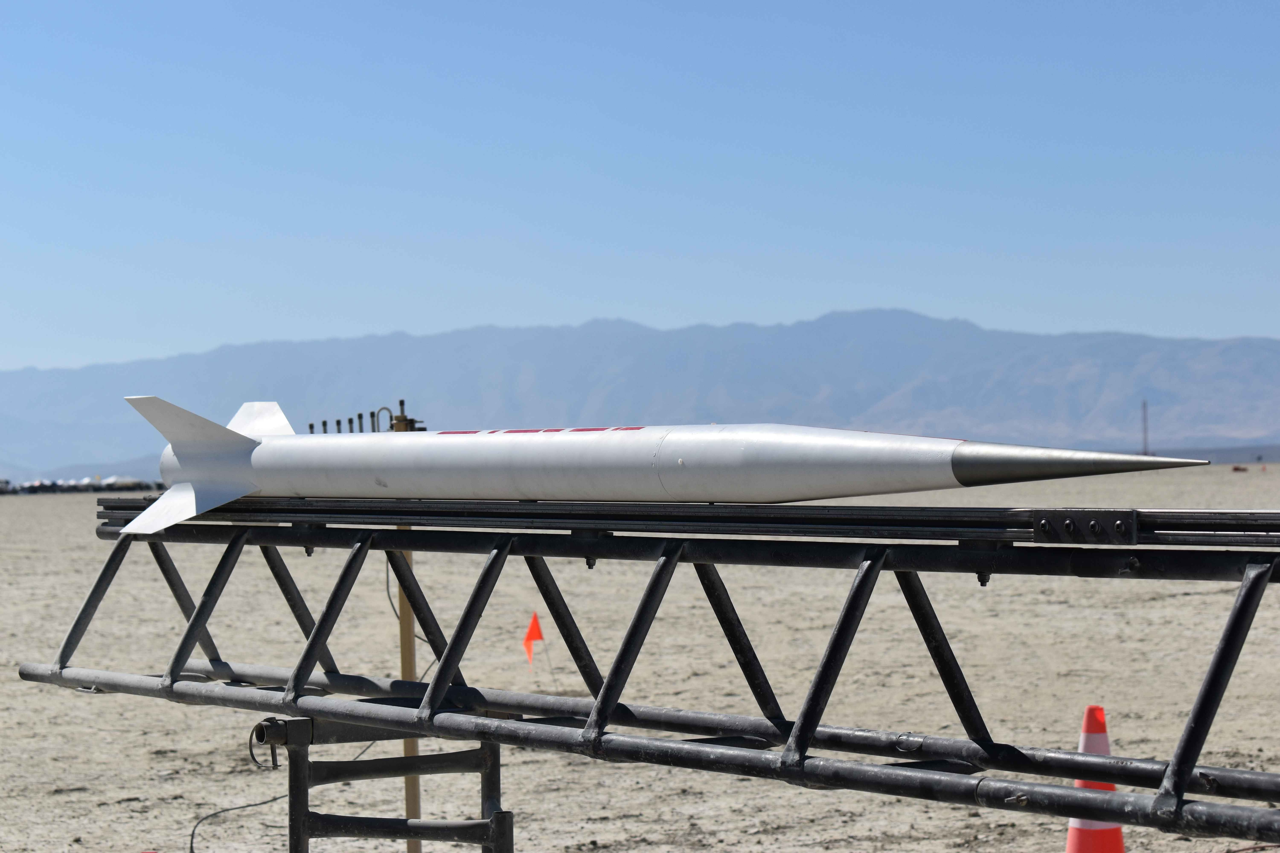
Thin Red Line
Goal: 90,000’ AGL, Mach 4.0, Successful Recovery.
Thin Red Line was our second fully integrated flight vehicle. Named after the delicate barrier between success and failure, it sought to push the margins of amateur rocketry using novel motor and aerostructure architectures. Launched at BALLS 32 in September 2024, it flew on a modified ABLATE-O6000. Due to a thermal failure of the motor, the flight was ultimately unsuccessful but did serve as a proving grounds for future projects.
Details
The design of Thin Red Line had several goals:
Break Mach 4.
Fly above 90,000’ AGL.
Test high altitude recovery using single-separation deployment.
Verify new construction techniques.
Even though the flight ended in failure, some of these goals were met. In the following sections, each system of the rocket is discussed.
Propulsion
The powerplant was a modification of the ABLATE-O6000 motor. This motor failed its static test fire on the ground due to a thermal event initiated at the forward seal of the motor. Due to time constraints, a fix was formulated and implemented into the flight configuration of the motor. More information can be found on the motor’s page, but the architecture of the motor revolved around case-bonding the propellant. The motor was powered by Fatboy, our bismuth propellant. It utilized an 8-point finocyl at the forward end of the motor to neutralize the thrust curve, which transitioned to cylindrical geometry towards the aft end of the motor. The insulator was spun cast into the casing, after which the propellant was poured and sealed at both ends with more insulator.
Motor static test fire.
Aero Structures
Fins
To decrease part count, lower cost, and increase performance, Thin Red Line used machined full double-wedge aluminum fins bonded onto the motor casing using an in-house developed chemical surface treatment. The fins were first tacked onto the aft-end of the casing, at which point the etching solution was applied to both the fin root chord and the motor casing. After sufficient time had elapsed, the solution was removed, the components were cleaned thoroughly, and the fillet was pulled. Pictures showing this process are provided below:
Fins tacked onto motor casing.
Complete avionics sled back.
Machined ablative nozzle.
Etching solution applied.
Fillets pulled.
Avionics sled base.
The recovery system was configured to single-separation deployment. Unlike Nuka-Cola, this cut down the moving parts of the system by half. Instead, redundant cable cutters were installed around the main parachute. A drogue would deploy at apogee, and at a set distance during descent the cable cutters would release the main parachute. Unfortunately, this system was not activated during flight due to the motor malfunction, but all pieces were recovered.
The avionics were forward-mounted in the nose cone to provide RF transparency for the radios. To retain the avionics bay, a clevis was attached on the forward end, to which the nose cone tip threaded into. The base of the electronics bay was a tapered SLS nylon part, which interfaced with the inner face of the nose cone shell. As the nose tip was tightened, it pulled the tapers together resulting in a rigid friction seal. The recovery harnessing was then joined to the base of the avionics bay. For this to be possible, the avionics bay sled was necessarily a structural member of the system. It was composed of laser-cut 7075-T6 aluminum to provide margin in the bearing strength for the clevises.
For the flight computers, we used an AIM XTRA 4.0 as the primary altimeter and tracker, a FeatherWeight as the redundant tracker, and a timer as the redundant deployment device. All three were mounted on the aluminum avionics sled and maintained radio lock throughout the entirety of the flight.
Electronics & Recovery
Complete avionics sled front.
Spun cast insulator.
Nose Cone
The nose cone was composed of two primary assemblies: the fiberglass shell and the machined aluminum tip. The shell was constructed by laying up several layers of fiberglass sleeve onto a printed mold. By carefully controlling the amount of resin used, we achieved a fiber volume fraction of 50% without the use of vacuum or other compression methods.
Gallery
As-laid up cone.
Demolded cone.
The tip was fully machined from 6061-T6 aluminum and consisted of three separate components to reduce weight: the threaded base, hollow cone, and solid tip. All parts included machined threads to join them together. A threaded stud was installed at the base of the tip, which anchored at the forward clevis of the avionics sled (see below). This provided a rigid attachment for the nose cone tip while doubling as a retention and load-bearing mechanism for the the sled.
Nose tip configuration cross section.
Painted and completed cone.
Installed nose tip.
